Multi-constellation coverage
Covers common GPS, GLONASS and BeiDou frequency bands.

Home / High-Precision Antenna Systems
High-Precision Antenna SystemsDesigned for high-precision terminals, base stations and integrated equipment, with multi-constellation coverage, a stable phase center, RF performance and outdoor reliability.
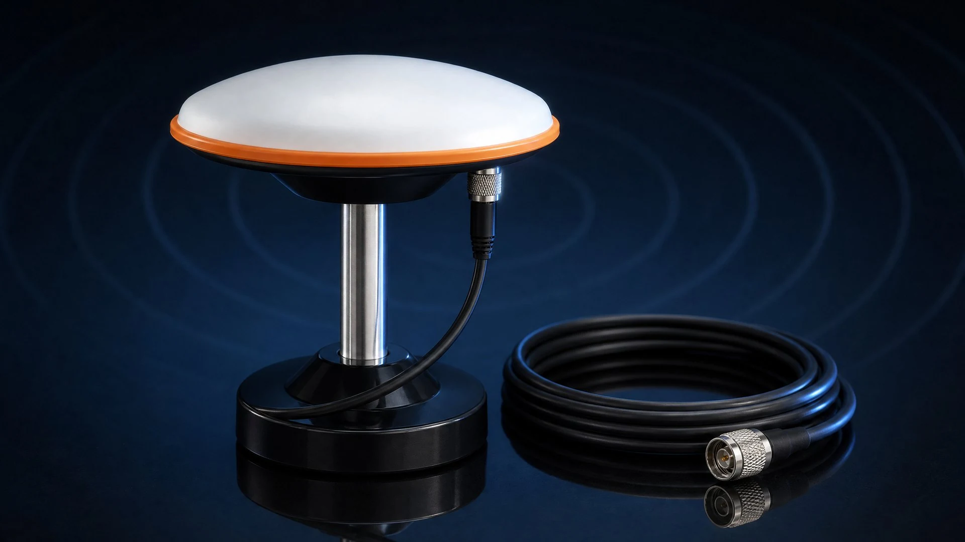
The high-precision antenna system is designed for high-precision positioning terminals, reference stations and integrated equipment, with attention to multi-constellation reception, phase-center stability and reliability in demanding environments.
It covers common GPS, GLONASS and BeiDou bands and provides RHCP polarization with 360-degree horizontal coverage for projects that require stable satellite signal reception.
| Item | Details |
|---|---|
| Frequency range | GPS L1/L2/L5/L-band; GLONASS G1/G2; BeiDou B1/B2/B3 |
| Zenith gain | >=5.5dBi |
| Phase center error | <+/-2mm |
| Voltage standing wave ratio | <=1.5 |
| Zenith axial ratio | <=3dB |
| Polarization and coverage | RHCP; 360-degree horizontal coverage |
| Impedance | 50 ohm |
| LNA gain | 40+/-2dB |
| Noise figure | <=1.8dB |
| Output standing wave ratio | <=2.0 |
| Differential delay | <=5ns |
| LNA current | <=48mA |
| Mechanical dimensions | D150 x H58.4mm |
| Connector | TNC-K |
| Weight | <=450g |
| Operating temperature | -45 to +70 C |
| Protection | IP67 |
Covers common GPS, GLONASS and BeiDou frequency bands.
A phase center error below +/-2mm supports high-precision positioning applications.
Balances gain, standing wave ratio, axial ratio and multipath-related performance.
Provides 40+/-2dB gain while controlling noise, standing wave ratio and differential delay.
Supports an operating range from -45 to +70 C with IP67 protection.
Configuration is confirmed for terminal, base-station or integrated-equipment requirements.
Provides antenna reception for survey, inspection and mobile positioning terminals.
Designed for continuously operating high-precision positioning infrastructure.
Used for positioning reception on UAVs, robots and autonomous platforms.
Fits industry equipment that requires stable GNSS signal reception.
The antenna sets the ceiling on a receiver's observation quality, so start with bands. Single-frequency is enough for standalone positioning; RTK fixed solutions, multi-constellation solving and multipath-heavy sites call for a multi-band antenna covering GPS L1/L2/L5, GLONASS and BeiDou. The YUEETEK SK6640 high-precision antenna system covers these bands with a built-in LNA.
For RTK base stations and all-band GNSS integration, review the GNSS industry applications and the ODM/OEM custom development process, then confirm connector, cable, mounting and environmental requirements with YUEETEK. The antenna can be evaluated alongside the customizable RTK GNSS module when the receiver and antenna are specified as one system.
Two specifications matter most: peak gain and phase-centre stability. Peak gain of at least 5.5dBi maintains carrier-to-noise ratio in weak-signal environments, while a phase-centre deviation under 2mm drives survey repeatability; VSWR, axial ratio and IP67 protection complete the picture. The full method is covered in our high-precision GNSS antenna selection guide.
For specifications, download the high-precision antenna systems datasheet (PDF); for complete systems compare the handheld GNSS RTK receiver and the customizable RTK module PCBA, or review the Product Selection Guide. Connectors, cabling and mounting are confirmed per project — contact us for pricing.
Ground plane and mounting position: A high-precision antenna needs a stable metal ground plane to preserve gain, axial ratio and phase-centre consistency. Reference stations and fixed base stations should use a sufficiently large ground plane or choke ring, with the phase centre clear of nearby metalwork; integrated terminals should reserve a keep-out zone below the antenna so batteries, shields and connectors do not enter the near field. Keep the antenna away from transmitters and strong reflectors, mount it as vertically as possible, and reduce multipath effects on C/N0 and RTK fixed solutions.
Mounting and cable loss: Survey-grade antennas are commonly mounted on a tripod, range pole or fixed mast. Confirm connector torque, waterproofing and lightning/earth bonding; vehicle and equipment installations must account for vibration, wind load and cable strain. Longer cable runs increase loss, and the difference between GPS L1 and L2/L5 attenuation can affect dual-band solving. Use low-loss coaxial cable, minimise adapters, and verify voltage and current headroom at the active-antenna power injector.
Acceptance checks: After installation, review C/N0 and visible-satellite count per band, then compare repeated measurements on a known point. Where multipath is obvious, re-test after changing the mounting position, enlarging the ground plane or adjusting antenna height. For project-specific connectors, cables, mounting adapters or outdoor protection, see our outdoor positioning guidance or contact us.
Click any image to inspect specifications, product details and application scenes.