Power and surge
A voltage dip at power-on can reset the module, presenting as intermittent satellite loss.
The difficulty in integrating a customizable RTK module is not the board itself, but whether power, antenna and protocol can all be resolved at once. Without clear boundary conditions in these three areas, the field can show intermittent satellite loss, slow fixes, or repeated rework during integration.
A voltage dip at power-on can reset the module, presenting as intermittent satellite loss.
Inadequate feeder length and grounding pulls the carrier-to-noise ratio down, and the fixed solution is slow.
A serial baud rate, data format, reporting rate or platform that does not match forces repeated rework during integration.
Confirm the machine power and surge boundaries first, then lock down the antenna, feeder and grounding scheme, and finally align the serial port, data format and platform reporting definitions. Leave each step re-testable so the problem stays within a controllable range.
Once the module is inside a machine, power is no longer only a question of voltage range. The power-up sequence, harness voltage drop, load steps and surges all enter the same supply chain. If the voltage at start-up falls below the module's operating boundary, the device may restart on its own, and on site this shows up as intermittent satellite loss that is hard to reproduce.
When integrating, leave a stable power margin first, then check wire gauge, connectors, the ground return and transient suppression. Sample tests should cover the real states of the machine, including cold start, the communication module powering up at the same time and load switching, not just powering the module on its own on a bench.
Antenna performance ultimately depends on the combined effect of the installation environment, feeder length, connector loss, grounding and shielding. Looking only at the antenna's own figures cannot tell you whether it will still receive satellite signals reliably once mounted on the machine.
During project validation, measure the change in carrier-to-noise ratio in the target structure, compare feeder and grounding options, and check whether there is obstruction or strong interference around the antenna. When the fixed solution takes longer to establish, review the RF chain and power stability together instead of adjusting only on the algorithm side.

The first mismatch between the host controller, the module and the platform is usually the serial baud rate, data format, reporting rate and message fields. Leaving the interface definition until the integration stage tends to affect the firmware, the platform and the acceptance scripts.
A steadier approach is to fix the interface protocol, data content, timestamps, exception handling and offline strategy at the prototype stage, and to complete a continuous run test at the actual reporting rate. This way, when a data gap appears, you can quickly tell whether it comes from power, the RF chain or the communication link.
Core configuration: UM980 + 4G + Bluetooth; 1408 channels (NebulasIV); supply range 5–30V.
Satellite frequencies: BeiDou B1I/B2I/B3I/B1C/B2a/B2b, GPS L1/L2/L5, GLONASS L1/L2, Galileo E1/E5a/E5b/E6, QZSS L1/L2/L5/L6.
RTK accuracy (RMS): horizontal 0.8cm+1ppm; vertical 1.5cm+1ppm.
Cold start: <20s.
The module supports OEM/ODM custom PCBA, quoted by project configuration, quantity and acceptance requirements.
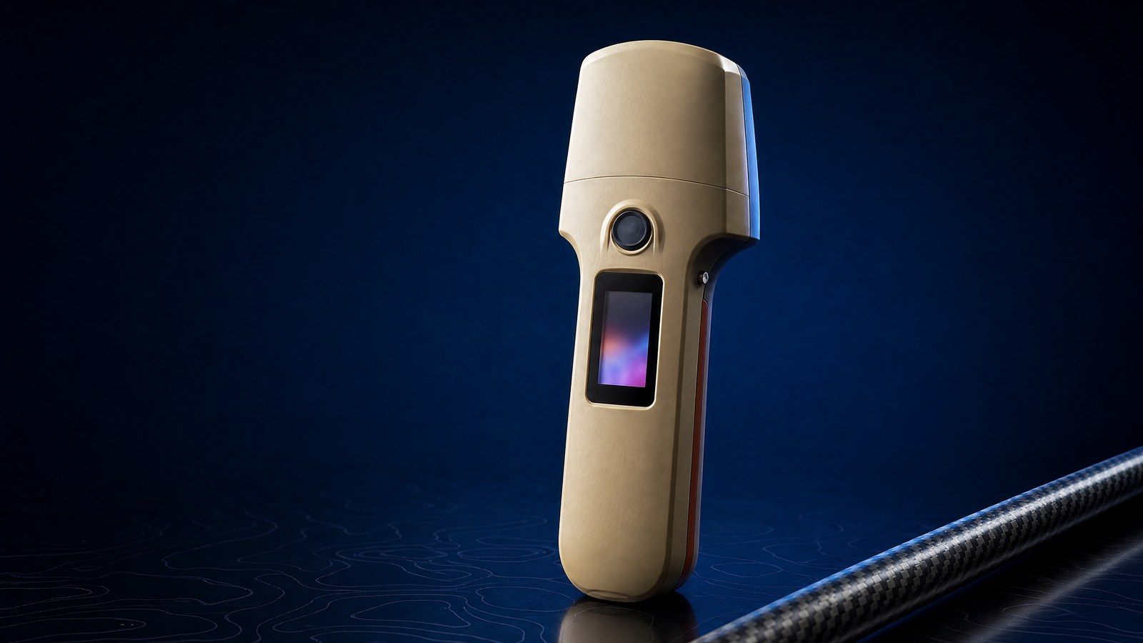
Current products (verified 2026-09-29): handheld H13 (multi-constellation, multi-frequency professional RTK handheld, single Pro tier); H11 (BeiDou-only, dual-frequency and Pro versions; H11 ProEU for Europe and H11 ProEN for North America overseas; brand name "Beidou Xingtan"); module MG20 (customizable RTK PCBA); antennas SK6640 and SK6608. The H11 Pro and H13 use the same module, both 1408 channels, NebulasIV.